Opinions questions about the use of Reinforced Concrete Design

Re: Opinions about the use of ideCAD Reinforced Concrete 8 questions
"MaFiAMaX":f8bh8psp" said:
Hello Mr.Hakan, As you mentioned, the best way to calculate punching is to consider only the concrete admixture. I asked for it to appear in the mold. It is visible when cut, but not in the mold plan. It would be nice if this feature is added :) I have sent the example about the curtain now. Good work.
Thank you for your feedback. Good work...
 
Re: Opinions about using ideCAD Reinforced Concrete 8 questions
"HakanŞahin":1bmusxb9" said:
Hello again,
"AYDIN":1bmusxb9" said:
Additions that appear in reinforcement expansions are not visible in the foundation section. And in the reinforcement expansions, the body reinforcement mortar does not write the names of the others.
Sections are taken from the middle of the opening in the openings. Look at the location of the section line, there are no additional reinforcements at the point where the section passes. We do not have the opportunity to pass the section line through the support. Good work
Hello, Mr. Hakan, I showed the yellow ---> sign where the additional equipment should be written but not written. It wasn't the part I was talking about.
 
Re: Opinions about using ideCAD Reinforced Concrete 8 questions
"AYDIN":15lnrfsu" said:
"HakanŞahin":15lnrfsu" said:
Hello again,
"AYDIN":15lnrfsu" said:
Reinforcement The additions visible in the foundation section are not visible in the foundation section. And the names of the shell reinforcement mortar others are not written in the reinforcement expansions.
Sections are taken from the middle of the opening in the openings. Look at the location of the section line, there are no additional reinforcements at the point where the section passes. We do not have the opportunity to pass the section line through the support. Good work[ /quote] Hello Mr. Hakan, I indicated the point where additional reinforcements should be written but not written with yellow ---> sign.It is not the section I mentioned. It will be put into the stirrup immediately like the flat reinforcement. Similarly, the upper reinforcements are in the same position as the assembly, not like the body. Therefore, in the side view of the beam, they are drawn together with the straight reinforcement as a single line. I hope a we have come to terms. If necessary, you can call me on 0 224 220 67 17 so that the subject does not go further.
 
Re: Opinions about the use of ideCAD Reinforced Concrete 8 questions My aim is not to prolong the subject or create polemics. Thanks to the forum, I learned many issues that I did not know about ide, which I did not know or knew wrongly. My goal is to contribute, even in a small way, to the development of the program we use. The situation you mentioned is valid for the beams, but there are additions written on the beams in the side view. At the same time, the name of assembly or flat reinforcement is written in the beam reinforcement openings. but in the basic beams, only the name of your body reinforcement is written in the reinforcement expansions. In the project I sent, I added a normal beam detail under the foundation beam. I marked the differences.
 
Re: Opinions about the use of ideCAD Reinforced Concrete 8 questions
"AYDIN":bdxjfgyb" said:
My aim is not to prolong the topic or to create polemics. I learned a lot about ide, which I did not know, missing or wrong, thanks to the forum. It is a small contribution to the development of the program we use. The situation you mentioned is valid for the beams, but there are additions in the side view on the beams. At the same time, the name of assembly or flat reinforcement is written in the beam reinforcement expansions. However, only the name of the body reinforcement is written in the reinforcement expansions in the foundation beams. I added a normal beam detail. I marked the differences.
Hello again Mr. Aydın, It is a known issue that we know that the foundation expansions are always made like beam expansions. Thanks for your feedback...
 
Re: opinions questions about using ideCAD Reinforced Concrete 8 Hello. Can't we take the horizontal reinforcements of the earth curtains in the picture to the end in the column they are stuck in? Doesn't it go into at least as much as the docking size?
You do not have permission to view link Log in or register now.
 
Re: Opinions about the use of ideCAD Reinforced Concrete 8 questions
"EmreT":i6cyu59s" said:
Hello. Can't we take the horizontal reinforcements of the earth curtains in the picture to the end in the column they are stuck in? ?
Hello, The reinforcement you mentioned is about the clamping length in lb. (You can check the total reinforcement length.) If the clamping length was larger than the column size, the reinforcement would be extended to the end of the column. Note : The lb length is calculated from the lb calculation given in TS500. Good work
 
Re: Opinions and questions about using ideCAD Reinforced Concrete 8 Mr. Hakan, Thanks for the reply. In the related drawing, the clamping length for concrete C40 and fi10 reinforcement is: lb=0.12* (fyd/fctd)*fi = 0.12 * (365 / 1.45) * 10 = 30cm. My measurement in the drawing is 26.5cm. I made a simple model and looked again and measured the same value. You can see it in the picture. I couldn't understand the error...
You do not have permission to view link Log in or register now.
 
Re: Opinions about using ideCAD Reinforced Concrete 8 questions Hello, Clamping starts from the inside of the panel, not from the column edge. 393- (340-2*4.5) = 62 and 62/2=31 cm. We will report the issue to arge for investigation. Thanks for our report...
 
Re: Opinions about using ideCAD Reinforced Concrete 8 questions Hello, I have a couple of problems; - The details of the stair sections we drew are very messy and bad. -It gives 90 cm sprout length to 50 cm curtains, which we define as sub-basement curtains.
 
Re: Opinions about using ideCAD Reinforced Concrete 8 questions Hello, I marked the naming direction from right to left so that the element brands in the blocks are similar in projects with symmetrical blocks. Although there were columns and floors, there were no beams. I couldn't understand the problem. An example model is attached.
You do not have permission to view link Log in or register now.
 
Re: Opinions about using ideCAD Reinforced Concrete 8 questions
"EmreT":2eno1u9a" said:
Hi, I marked the naming direction from right to left so that the element brands in the blocks are similar in projects with symmetrical blocks. I couldn't understand the problem. A sample model is attached.
Hello, Horizontal beams cannot be named from right to left, we will report the issue to R&D for review. Thank you...
 
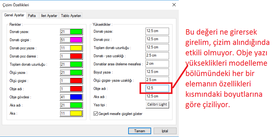
Re: Opinions about using ideCAD Reinforced Concrete 8 questions Hello, I am having a problem with adjusting the text height of the object (beam, column, etc.) elements while drawing. I am using v8.504. We draw 1/100 drawings that do not fit into 1/50 drawings. However, instead of blocking and shrinking the drawing, we always draw our drawings in real size. So 1 unit is always 1 cm. In this case, our 1/100 sheet frame becomes 2 times larger than 1/50. In this case, when the drawing in the larger frame is printed on A0 paper, the font height, which is 1/50, must be 2 times larger so that they can be read. While getting the mold plan, no matter what we do with the object name in the dialog that opens, it always comes up with the text heights in the object properties on the modeling screen. The reinforcement text height etc. can be taken at the desired text height. In the modeling screen, I think the font heights in the obe properties are only there so that they can be read on the modeling screen.
rEvz2P.png
NOTE: In the option to get drawing by creating a layout block, when the scale is written to the layout block, the drawing is reduced or enlarged accordingly. This is not what we want. Always draw in real size.
 
Re: Opinions about using ideCAD Reinforced Concrete 8 questions
"MaFiAMaX":1ld7hnon" said:
Hi, I'm having a problem adjusting the text height of the object (beam, column, etc.) elements while drawing. I'm using v8.504 We draw drawings that do not fit in 1/50 drawings as 1/100. However, instead of blocking and reducing the drawing, we always draw our drawings in real size. That is, 1 unit is always 1 cm. In this case, our 1/100 sheet frame is 2 times compared to 1/50 In this case, when the drawing in the larger frame is printed on A0 paper, the font heights, which are 1/50, must be 2 times larger so that they can be read.While getting the mold plan, whatever we do with the object name in the dialog that opens, we always use the text heights in the object properties on the modeling screen Reinforcement font height etc. can be taken at the desired font height. I think the font heights in the obe properties are only available on the modeling screen so that they can be read on the modeling screen. [i mg]http://i.hizliresim.com/rEvz2P.png[/img] NOTE: In the option to get drawing by creating a layout block, when the scale is written in the layout block, the drawing is reduced or enlarged accordingly. This is not what we want. Always drawing in real size.
Hello Mr. Erhan, There is no possibility to set the scale at once as you want in the program. As you wrote, beam, column writings, etc. are the elements that can be determined in the object properties. The options given in the drawing properties are mostly effective for beam expansions.
 
Re: Opinions about the use of ideCAD Reinforced Concrete 8 questions Greetings, Mr. Hakan, I think there is a deficiency in the software. Because when the column takes the application plan as 1/100 instead of 1/50, it draws the drawing 1-1 as it should be, but draws the text heights as 2 times the values in the current window. So it's doing as it should. But no matter what you do to scale the mold plan drawing, it has no effect. Could there be an error in this section due to updates?
 
Re: Opinions about the use of ideCAD Reinforced Concrete 8 questions
"MaFiAMaX":32s5e33v" said:
Greetings, Mr. Hakan, But no matter what you do to scale the formwork plan drawing, it has no effect. There may have been an error due to updates in this section is it?
No it's not update related, scale is not active for die plan. It was not active in any version either.
 
Re: Opinions about the use of ideCAD Reinforced Concrete 8 questions
"HakanŞahin":tlxqtz6n" said:
"MaFiAMaX":tlxqtz6n" said:
Greetings, Mr. Hakan, But whatever you do, the scale will have an effect it doesn't happen. Could there be an error in this section due to updates?
No, it is not related to the update, scale is not active for the die plan. It was not active in any version.
If it's not a difficult edit, I hope it will be active in the next version :)
 
Re: Opinions about using ideCAD Reinforced Concrete 8 questions
"MaFiAMaX":3bc98vb6" said:
"HakanŞahin":3bc98vb6" said:
"MaFiAMaX":3bc98vb6" said:
Greetings, Mr. Hakan, However, while taking the mold plan drawing, the scale has no effect no matter what you do. Could there be an error due to updates in this part?
No, it is not related to the update, the scale is not active for the mold plan. If it's not an edit, I hope it will be active in the next version :)
Every request written here is considered for future versions.
 
Re: Opinions and questions about using ideCAD Reinforced Concrete 8 Imports and exports from autocad are very successful. It makes working with architects extremely easy. (I put a plugin from the 3d export of a large business center to autocad) However, in some projects (intensive import is used) it is very difficult to collect the layers under the "standard" layer. The "rebar" layers that are locked may be back to the "standard" layer when I change the window and open the current window again. Good work
 
Re: opinions questions about using ideCAD Reinforced Concrete 8 Hello. We can divide the raft foundations of different thicknesses from the models by the slab edge and give both foundation thicknesses separately. Only when taking the drawing, it is seen that the bottom reinforcement coming from the 80cm thick foundation penetrates into the 40cm foundation as seen in the picture. Is this a problem because we divide the foundation by the slab edge? The relevant model is attached.
You do not have permission to view link Log in or register now.
 
Back
Top