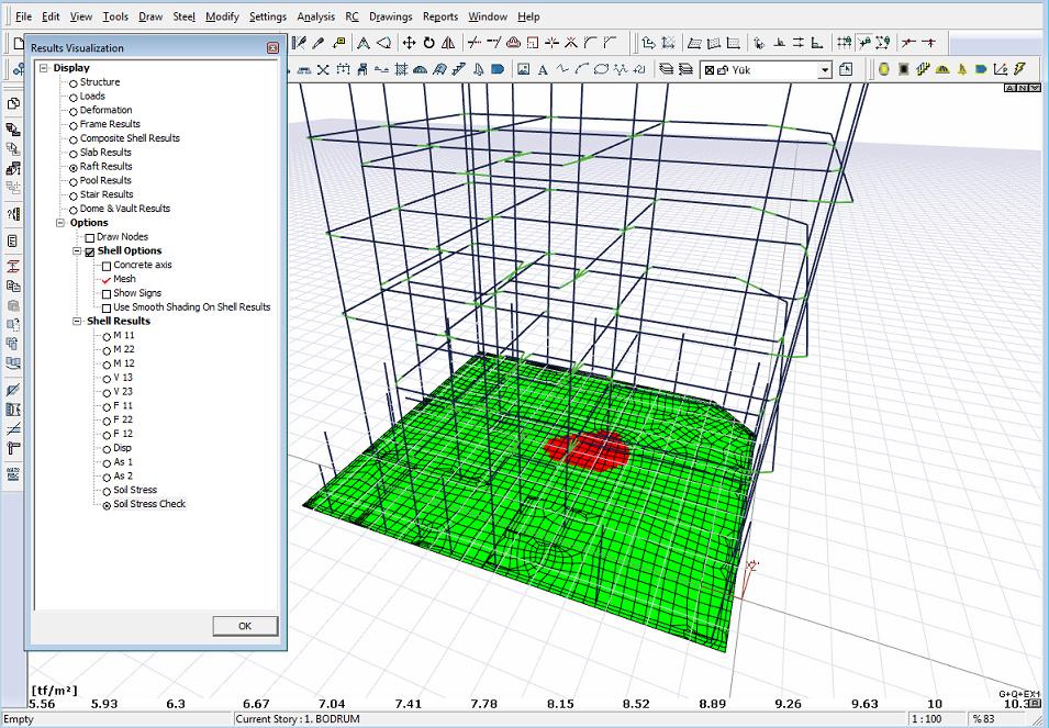
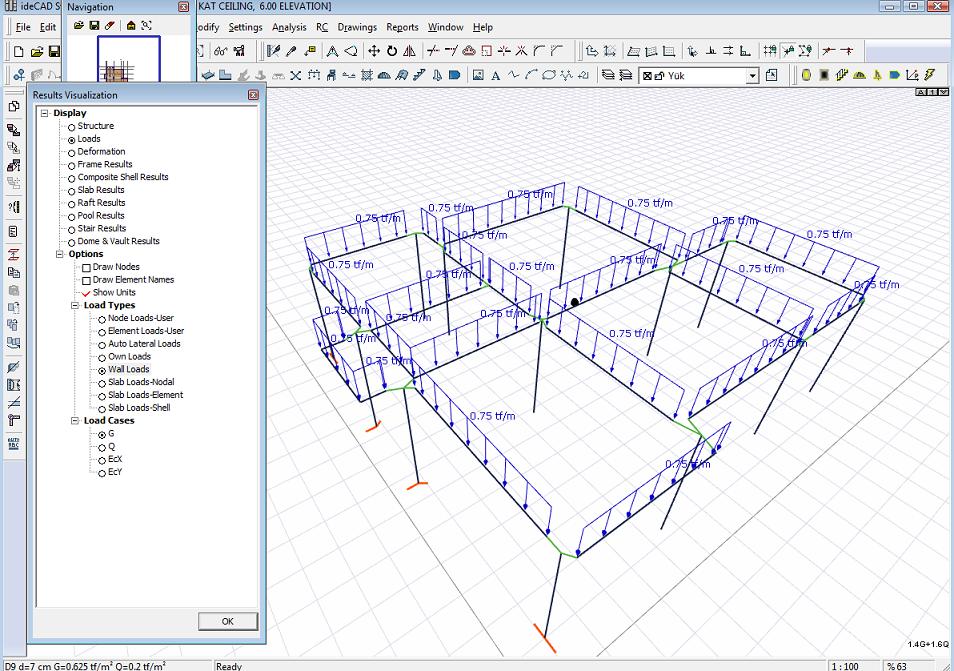
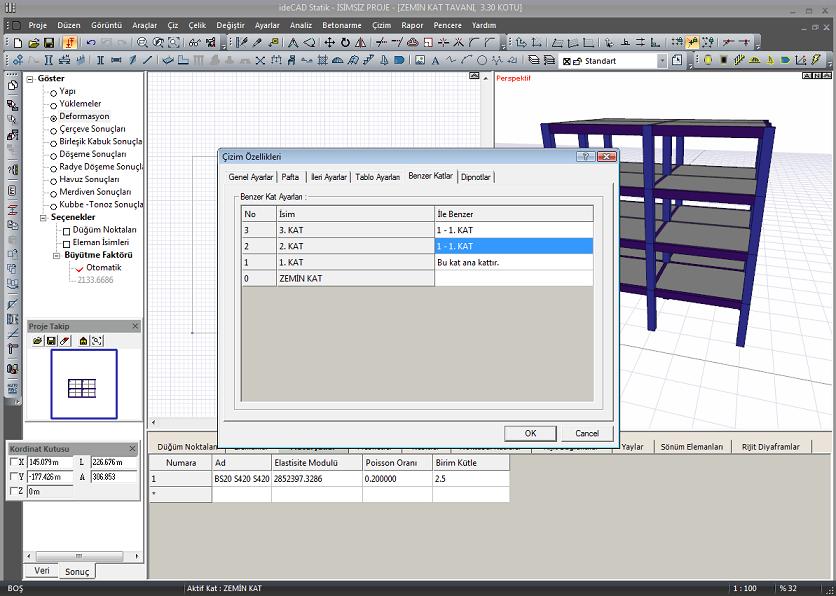
A few screenshots (currently in development) of the new dynamic analysis possibilities of v6.0500, which will be available in a few months. Oblique rigid diaphragms, and auto-detected rigid diaphragms review mode
New project analysis option using only the response spectrum solution. Real dynamic analysis.
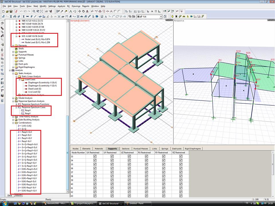
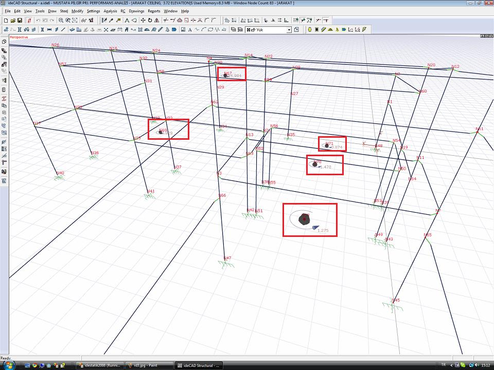
v6 users will say that the Response Spectrum solution is already being done, to summarize briefly for those who haven't had the opportunity to use v6 yet -v6 is now on a floor basis floor horizontal earthquake force is not calculated. Two response spectrum solutions, called Response-X and Response-Y, are made, and then the horizontal forces acting on the floors are calculated from the sum of the shear forces resulting from the spectral analysis of the vertical carrier elements on the relevant floor. (Similar to the use of the section cut command in SAP2000 - but the program does it automatically, starting from the floor information). Later, these horizontal forces were applied to the floors, taking into account the eccentricity, and a static solution was made again. An important innovation in terms of analysis in v6.0050 is that all design and regulation controls can be made automatically according to the combination of effects arising from the Response solution + eccentricity. You can also solve your projects that do not have a rigid diaphragm correctly in v6 with the Response Spectrum method. You can see the moments.
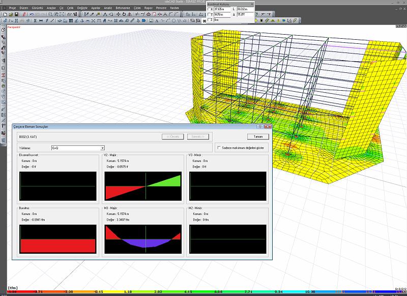
As expected from real response spectrum analysis, element end forces and deformations come out as absolute values.(CQC method is a statistical effect coupling method).
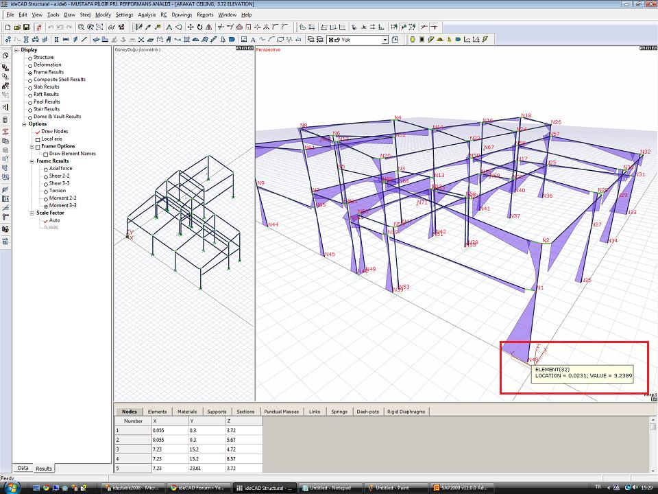
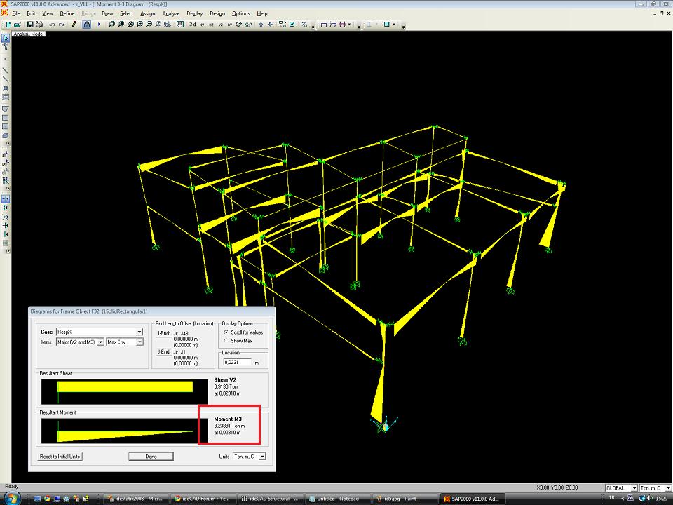
Complete transfer of the project to SAP2000 with all elements, analysis cases and combinations and comparison of results.
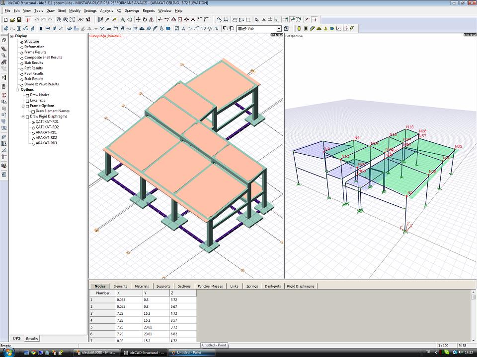
You can also find traces of v6's most important design philosophy in these screenshots, loads that the program automatically defines in your project, diaphragms, bar system, sections, Shells, materials, etc. are not hidden, as an engineer, they are at your fingertips like any other general purpose analysis program. Note: Project Mr. Ins. Eng. It belongs to Mustafa ÇALI.
 New project analysis option using only the response spectrum solution. Real dynamic analysis.
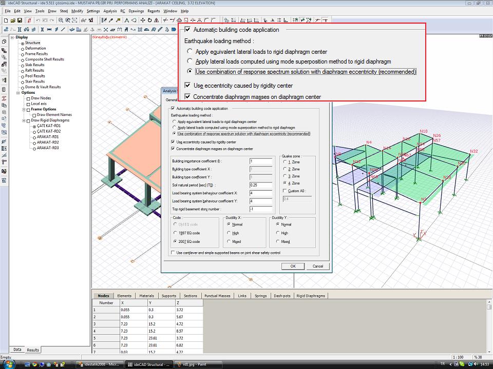 v6 users will say that the Response Spectrum solution is already being done, to summarize briefly for those who haven't had the opportunity to use v6 yet -v6 is now on a floor basis floor horizontal earthquake force is not calculated. Two response spectrum solutions, called Response-X and Response-Y, are made, and then the horizontal forces acting on the floors are calculated from the sum of the shear forces resulting from the spectral analysis of the vertical carrier elements on the relevant floor. (Similar to the use of the section cut command in SAP2000 - but the program does it automatically, starting from the floor information). Later, these horizontal forces were applied to the floors, taking into account the eccentricity, and a static solution was made again. An important innovation in terms of analysis in v6.0050 is that all design and regulation controls can be made automatically according to the combination of effects arising from the Response solution + eccentricity. You can also solve your projects that do not have a rigid diaphragm correctly in v6 with the Response Spectrum method. You can see the moments.

![img]](http://www.idecadsupport.com/diger/050b.jpg[ /img])