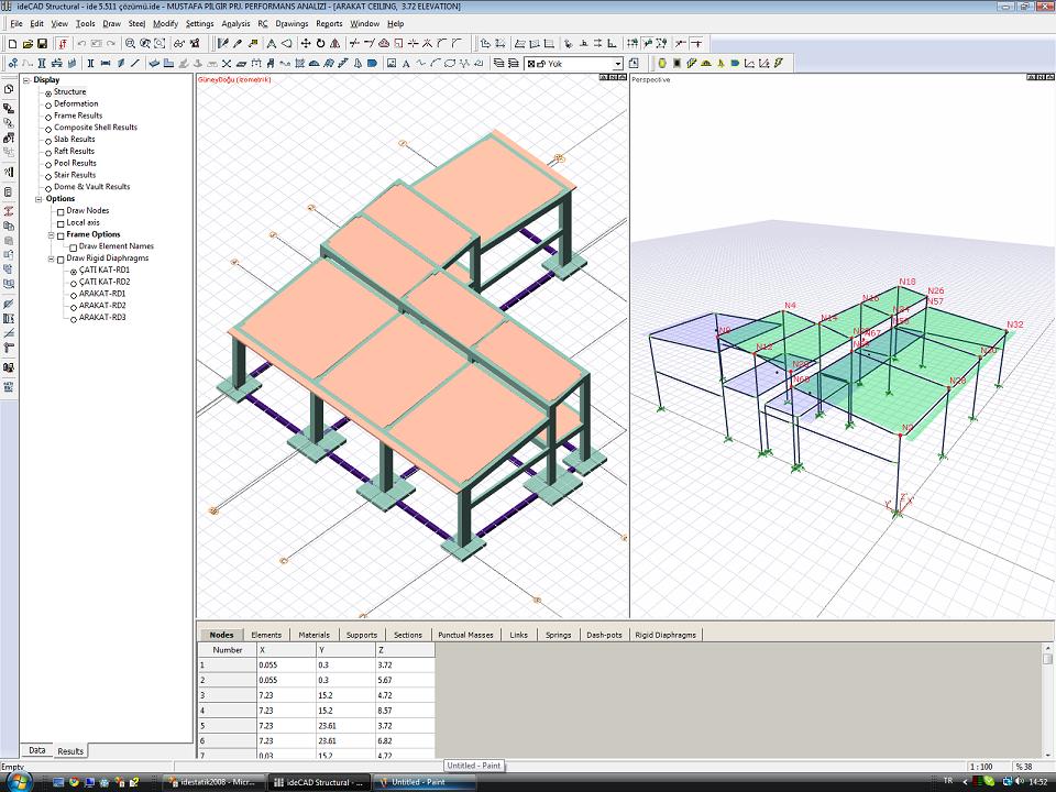
Dear Sir/Madam, I made the attached project with the aim of strengthening it in version 5. On the floors of the building, there is a 1 meter elevation difference in both parts of the floor area. In this case, two different levels should form two different rigid diaphragms, but I saw 6 rds on the ground floor and 4 rds on the 1st floor. 2 rd formed on other floors. This must not be true. If these rds are taken into account in the analysis, I think there will be erroneous results. I'll be pleased if you pay attention. I just downloaded version 6 and started a new review. The tree structure is the element, node, etc. that we want to examine in the menu. I think it would be easier to use the menu if the related element was selected in the structure when it is selected. Take it easy, thank you Suat Yıldırım
You are using an out of date browser. It may not display this or other websites correctly.
You should upgrade or use an alternative browser.
You should upgrade or use an alternative browser.
give 6 automatic rigid diaphragms
- Thread starter suatyy
- Start date
cassabotanic
New Member
When there are rigid diaphragms found (not found) by the program, you can determine the rigid diaphragm contour yourself, or you can calculate according to a single rigid diaphragm on each floor, as in version 5. I also came across this situation in some projects and reported it to ideYAPI. They will fix this situation.
Thank you for your answer. I already did it this way, but when defining the contours, he didn't ask for jeans. I couldn't find how to give which elevation rd is at. When I look from the 3d frame, I see that the rd center is at the correct elevation, but I did not give this elevation. even if he buys from the floors, he is not in this project, but when there are two different floors on the level where the ord is located, he may get the wrong level, I think it would be more accurate to define jeans by us.
Hello friends; I have encountered this kind of problem before and I realized that I had done the data entry of that project in version 5. I have yet to encounter such a problem in a project defined with V6. If you have such a situation, my advice is to delete all tiles and redefine them in V6. In addition, in manually defining the diaphragm, the program takes the nodal points within the contour as a single diaphragm, regardless of the elevation difference on the floors within the drawn contour, and makes the solution accordingly. I wish you good work...
Mr. Suat, there is an error in the contour of the DB89 slab on the ground floor in the project you added. When it recreates this slab and the DB90,91,92 tiles on the 1st floor, it correctly detects the rigid diaphragms. In version 6.0011 the automatic detection of rigid diaphragm is done through the floor controls (for version 6.0050 we have developed an algorithm that is more tolerant of this type of data entry error), so re-entering the tiles that are causing problems should be the first thing to consider. In general, such situations may arise as a result of subsequent manipulations in systems with previously entered tiles.
As of version 6, the program recognizes slab discontinuities, automatically finds different rigid diaphragms in your building and sets up the carrier system accordingly. For example, in the above example project, there are 2 different rigid diaphragms due to the elevation difference.


